Contents
- 01What Is a Tube Amp, and Why Does It Still Matter?
- 02How Does a Tube Amp Work, The Full Signal Path, Step by Step
- 03Inside a Vacuum Tube, The Physics
- 04The Power Supply, Where All That High Voltage Comes From
- 05Single-Ended vs. Push-Pull, Two Ways to Build the Output Stage
- 06Why Tube Amps Distort, and Why Guitarists Love It
- 07Tube Amp vs. Solid State, What's Actually Different
- 08Real Tube Amp Circuit Walk-Through: Fender Deluxe Reverb AB763
- 09Bias, The Setting That Determines How Your Output Tubes Run
- 10The Output Transformer as a Tone-Shaping Device
- 11Frequently Asked Questions
- 12Where to Start
At the input jack, a typical single-coil pickup delivers somewhere between 100 and 150 millivolts RMS. That’s not enough to move a speaker cone a fraction of a millimeter. By the time that same signal reaches the output transformer, it’s carrying 22 watts, 40 watts, or more. The gap between those two numbers is the entire job of a tube amplifier, and understanding how tubes bridge that gap explains why certain amps feel the way they do, why a cranked blackface Deluxe Reverb sounds different from a clean solid-state amp at the same volume, and why guitarists have been arguing about output transformers since 1955.
Here’s the complete picture, from physics to speaker cone.
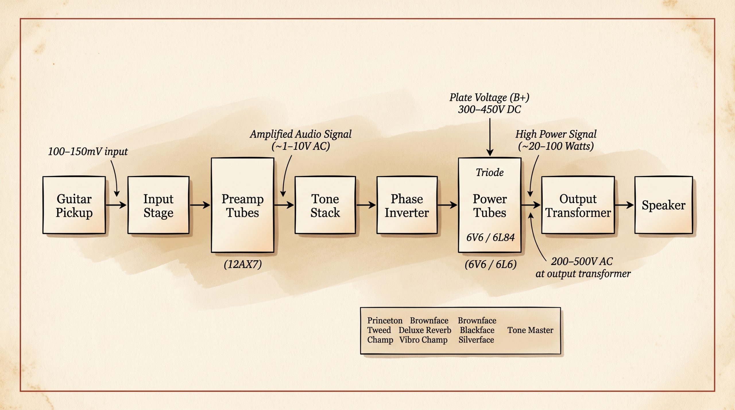
- Signal path: Guitar pickup → input stage → preamp tubes → tone stack → phase inverter → power tubes → output transformer → speaker
- Guitar signal at input: 100–400 mV (millivolts) depending on pickup type
- Signal at output transformer primary: 200–500V AC, depending on amp class and power rating
- Most common preamp tube: 12AX7 (µ = 100, gain per stage ≈ 30–60× in practice)
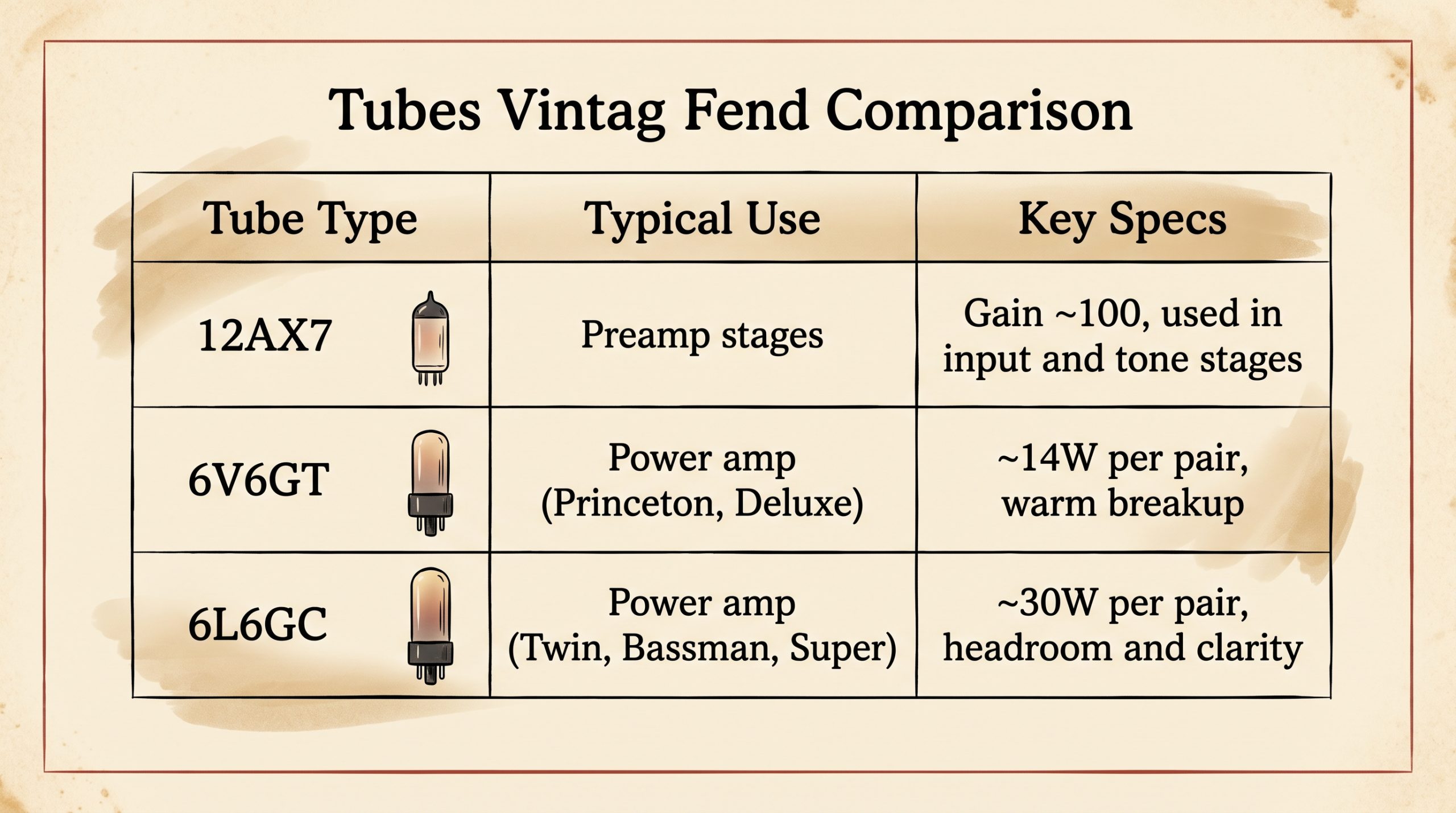
- Most common Fender power tubes: 6V6GT (Princeton, Deluxe) and 6L6GC (Twin, Bassman, Super)
- Output transformer matches power tube impedance (3,000–8,000Ω) to speaker impedance (4, 8, or 16Ω)
- Tube amps run at 250–500V B+ internally, lethal. Never service a tube amp without proper training.
- Output tubes wear out: typically 500–2,000 hours under regular use. Fixed-bias amps require rebiasing when tubes are replaced.
- Tube amp “watts” are not the same as solid-state watts at equal perceived volume, tube clipping behavior and low damping factor change how the speaker loads and responds.
What Is a Tube Amp, and Why Does It Still Matter?
A Brief History
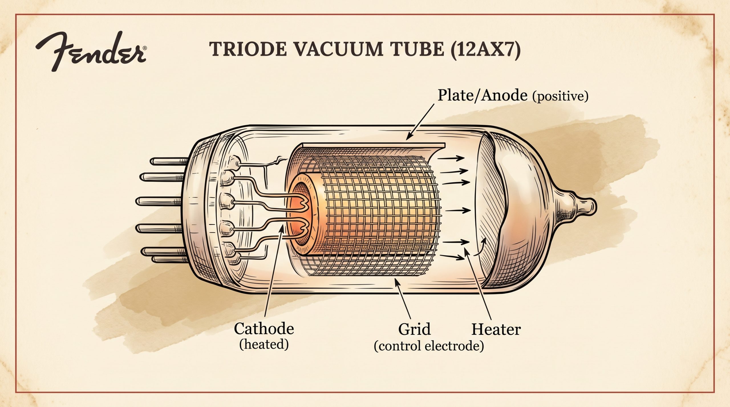
In 1906, Lee De Forest patented the Audion triode, the first device capable of amplifying an electrical signal. He placed a wire mesh (the grid) between a heated cathode and a positively charged anode inside an evacuated glass envelope, and discovered that small voltages on the grid produced large changes in current flow from cathode to plate. Amplification was born.
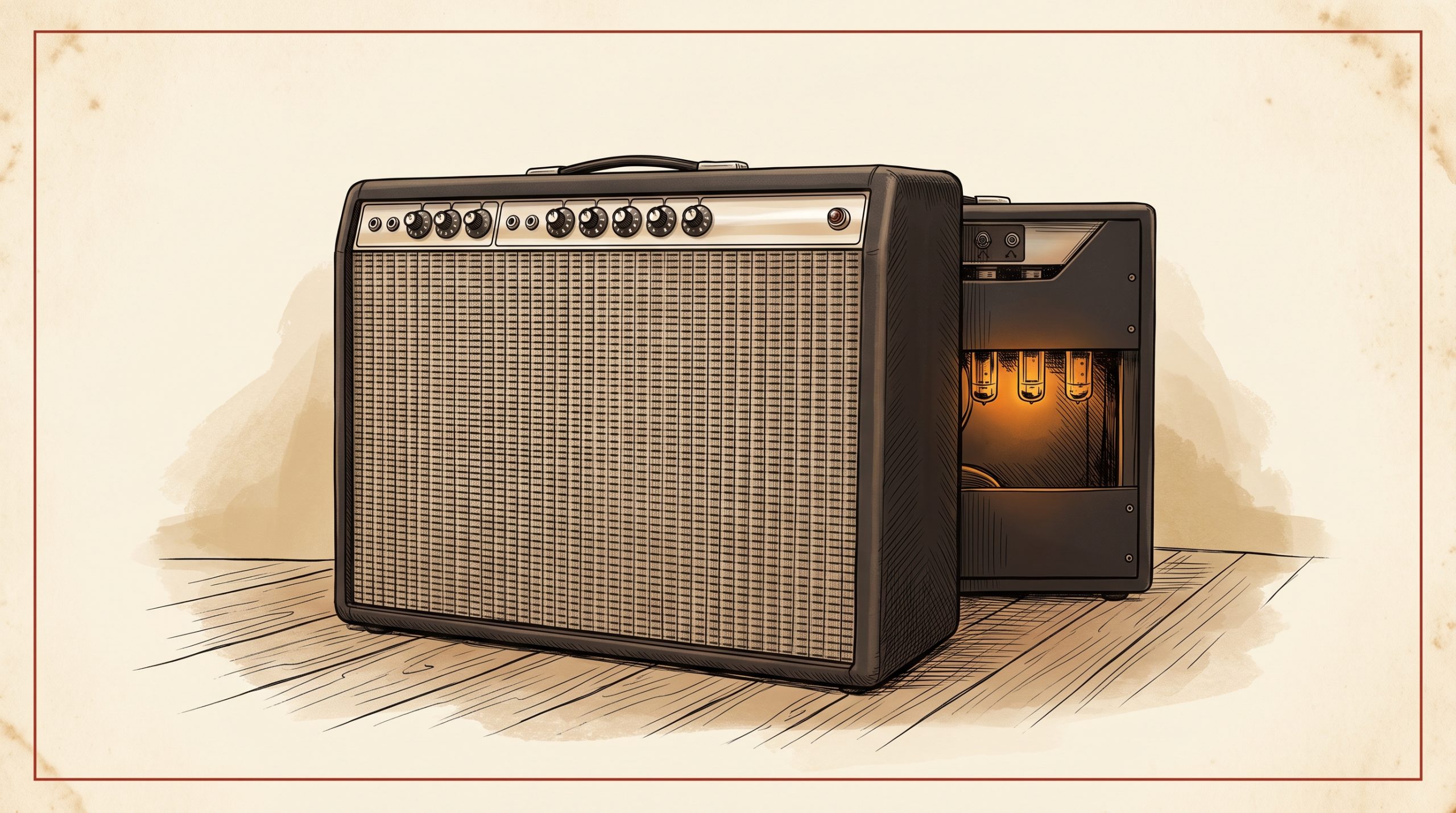
By the 1930s, that same principle was being used in the first guitar amplifiers. Through the 1940s and 1960s, Fender, Marshall, and Vox built their entire catalogs around tubes. When solid-state amps arrived in the 1970s, the tube was supposed to die. It didn’t. Nearly every recorded tone that defined rock, blues, and country from 1950 onward came from a tube amp, and the technology’s tactile, touch-sensitive behavior still hasn’t been convincingly replicated in a box that weighs under 10 pounds.
Who Still Uses Tube Amps?
Jimi Hendrix ran Marshall Plexis. Stevie Ray Vaughan played through Dumbles and original Vibroverbs. Jimmy Page’s “Whole Lotta Love” came from a Marshall 1959 Super Lead. Joe Bonamassa rotates through multiple vintage Fenders on any given tour. The list isn’t a nostalgia argument, it’s a documentation of why the gear keeps coming back. The tones on those recordings were products of specific physics, not just era preference.
How Does a Tube Amp Work, The Full Signal Path, Step by Step
The guitar signal entering your amp is around 100–300 millivolts, a tiny, rapidly oscillating AC voltage that mirrors string vibration. The amp needs to raise that to several watts of power. It does this in stages, each one handing off a progressively stronger signal to the next.
Step 1, The Guitar Pickup
Single-coil pickups output roughly 100–150 mV RMS under playing conditions. Humbuckers push 200–400 mV. The signal is alternating current, a waveform that swings positive and negative at audio frequencies, shaped by the vibrating string. That AC voltage enters the amp through the input jack and immediately hits a voltage divider network.
Step 2, The Input Stage and First Preamp Tube
Before the signal reaches the first tube, it passes through the input-jack network. A standard two-input Fender circuit ties Input 1 to a 1MΩ resistor to ground, while Input 2 sits behind a pair of 68kΩ resistors that bridge the two jacks together. Plugging into Input 2 drops the impedance the pickup sees to roughly 136kΩ and cuts the signal by about 6dB, useful with hotter pickups or when extra headroom is needed.
The first amplifying device in the chain is almost always a 12AX7 dual triode. The 12AX7’s amplification factor (µ) is 100, the highest of any common dual-triode preamp tube. In practical circuit operation with real load resistors, each triode stage delivers voltage gain of roughly 30–60 times. A 150 mV guitar signal becomes 1–5V after the first stage. For a deeper look at what separates the 12AX7 from alternatives like the 12AU7 and 12AT7, the 12AX7 tube guide covers the full specs and substitution options.
The Volume or Gain control on most amps sits at or immediately after this first gain stage, acting as a variable resistor that determines how much of the amplified signal passes forward.
Step 3, The Tone Stack
After initial gain, the signal passes through a passive tone stack, a network of resistors and capacitors that shape frequency response. Fender’s classic TMB (treble-mid-bass) stack, derived from the 5F6-A Bassman circuit, works by cutting frequencies rather than boosting them. There is no active amplification in the tone stack. A fully “scooped” mid position on a Fender TMB stack can reduce the signal by 15–18 dB. That loss has to be recovered in the next gain stage.
Step 4, Additional Preamp Stages
Most guitar amp preamps run two or three gain stages total. The Fender AB763 Deluxe Reverb uses four 12AX7 tubes across its Normal and Vibrato channel gain stages, reverb recovery, and vibrato oscillator, plus two 12AT7 tubes handling the reverb driver and phase inverter. By the end of the preamp section, the signal voltage can reach 20–80V AC. Still not enough power to drive a speaker. Still not done.
Step 5, The Phase Inverter
The phase inverter (PI) splits the single amplified signal into two identical signals with opposite polarity. These feed the two sides of the push-pull output stage. Fender blackface and silverface circuits (AB763, AA764, AA270, etc.) use a long-tailed pair phase inverter, built around a 12AX7 or 12AT7. Tweed-era Fenders like the 5E3 Deluxe use a simpler cathodyne (split-load) phase inverter. Not a trivial difference. The PI’s behavior under clipping is a major contributor to how an amp feels when pushed. A cathodyne PI clips asymmetrically, which is part of why the 5E3 has that distinctive lopsided compression character.
Step 6, The Output Stage (Power Tubes)
Power tubes handle a fundamentally different job than preamp tubes. Instead of voltage gain, they deliver current gain, converting a high-voltage, low-current signal into a high-current output capable of driving a transformer and speaker. Fender used two main power tubes across its classic lineup:
- 6V6GT: 14W maximum plate dissipation, plate voltage typically 350–400V, used in pairs (Princeton Reverb, Deluxe Reverb) for 18–22W Class AB output
- 6L6GC: 30W maximum plate dissipation, plate voltage typically 450–480V, used in pairs or quads (Super Reverb, Twin Reverb, Bassman) for 40–85W Class AB output
The 6V6 vs. 6L6 comparison goes deeper into how these two tubes differ in character at comparable volume levels. Short version: the 6V6 compresses earlier and breaks up sooner, the 6L6 runs cleaner longer and has a stiffer bass response.
Step 7, The Output Transformer
Power tubes have an output impedance of roughly 3,000–8,000 ohms. Speakers run at 4, 8, or 16 ohms. Connecting them directly would transfer almost no power, the impedance mismatch would swallow the signal. The output transformer solves this by stepping voltage down and current up using its turns ratio. An AB763 Deluxe Reverb output transformer runs a 6,600Ω primary to an 8Ω secondary, a turns ratio of approximately 28.7:1. It also blocks DC from reaching the speaker voice coil. The output transformer codes on vintage Fender amps can be decoded to confirm originality and date the unit, the Fender transformer date code guide covers the full EIA 606 decoding method.
Step 8, The Speaker
The speaker receives the amplified AC signal and converts it back into mechanical motion via an electromagnetic voice coil suspended in a magnetic field. Current through the coil creates force, the coil moves, the cone moves, air moves. That’s your guitar tone. A 12″ speaker in a vintage Fender, a Jensen C12N in many blackface Deluxe Reverbs, an Oxford 12L6 in others, moves its cone 1–4mm at high volumes. The speaker’s own efficiency, resonance frequency, and breakup characteristics contribute significantly to final tone. Not just a passive transducer. An active part of the sound.
Inside a Vacuum Tube, The Physics
What’s Actually Inside the Glass
The glass envelope is evacuated to a pressure of roughly 10⁻⁶ to 10⁻⁸ torr, close enough to a perfect vacuum that almost no air molecules remain to impede electron flow. Inside are three key elements in a triode:
- Cathode: heated to 800–1,000°C by an internal heater filament. At that temperature, electrons boil off the surface via thermionic emission.
- Control grid: a wire mesh positioned between cathode and plate. A small voltage on the grid controls the flow of electrons with very little power required, this is where the input signal is applied.
- Plate (anode): positively charged; collects the electrons that pass through the grid. The current flowing into the plate is the amplified signal.
A pentode adds a screen grid and a suppressor grid to the triode structure. The screen grid accelerates electrons toward the plate; the suppressor repels secondary electrons back to the plate. Result: higher efficiency and higher gain than a triode at equivalent plate dissipation. Pentodes are used in output stages (6V6, 6L6, EL34, EL84). Triodes are used in preamp stages (12AX7, 12AT7, 12AU7).
The Triode Equation in Plain English
A change of 1V on the control grid can produce a change of approximately 100V on the plate of a 12AX7 under typical operating conditions, that’s the µ = 100 figure you’ll see on datasheets. In real circuit operation, after accounting for load resistors and cathode bypass capacitors, the usable voltage gain per triode stage is 30–60×. Compare that against the other common preamp tubes:
| Tube Type | µ (Amplification Factor) | Typical Stage Gain | Common Application |
|---|---|---|---|
| 12AX7 | 100 | 30–60× | Preamp gain stages, reverb driver |
| 12AT7 | 60 | 25–45× | Phase inverter, reverb recovery |
| 12AU7 | 17 | 8–15× | Driver stages, lower-gain applications |
| 12AY7 | 40 | 20–35× | Tweed-era Fender input stages (5E3) |
Triode vs. Pentode in a Guitar Amp Context
Pentodes (6V6, 6L6, EL34, EL84) dominate output stages because of their higher efficiency. A triode output stage wastes more power as heat. That said, some amps, like the Fender 5F1 Champ, use a triode-wired 6V6 in a single-ended output stage. The result is softer, more compressed distortion with a higher proportion of even-order harmonics. Pentode operation in the output stage produces more odd-order harmonic content when pushed. Even-order harmonics are octaves and fifths, musically consonant. Odd-order harmonics are sevenths and ninths, more dissonant, more “gritty.” This is why triode-mode amps feel smooth and pentode amps bark when pushed.
The Power Supply, Where All That High Voltage Comes From
Rectifier Stage
Mains AC power (120V in North America, 240V in the UK and EU) enters the power transformer, which steps voltage up to 300–700V AC for the plate supply rail. That AC must be converted to DC before the tubes can use it. A rectifier handles this conversion.
Tube rectifiers (5Y3, 5AR4/GZ34, 5U4) have internal resistance that produces “sag”, a momentary voltage drop under heavy load when the output tubes demand sudden current. That sag is responsible for the compressed, bloomy feel of a hard-driven blackface Fender. The GZ34 rectifier guide explains the sag behavior and voltage drop specs in detail. Solid-state diode bridge rectifiers are stiffer, essentially instantaneous response with no sag, which produces tighter bass and more consistent headroom, but loses that soft-knee compression feel.
The AB763 Deluxe Reverb uses a 5AR4 (GZ34) tube rectifier, producing approximately 420V DC at the plates under idle conditions.
Filter Capacitors and B+ Voltage
Large electrolytic capacitors, typically 20–80µF at 450–550V rating, smooth the pulsating DC coming out of the rectifier into stable DC. Residual ripple that makes it through is audible as hum. The stabilized DC rail (called B+) feeds the plate voltage of preamp and output tubes.
The Fender AB763 Deluxe Reverb runs these voltages at stock:
- B+: approximately 420V DC
- Screen voltage: approximately 380V DC
- Bias voltage: approximately −42 to −50V DC (adjustable)
Filter capacitors are the most common maintenance item on a vintage amp. Electrolytic caps drift, dry out, and eventually fail after 30–40 years. A “re-cap” restores the original filtering behavior and removes hum that creeps in as caps age.
Single-Ended vs. Push-Pull, Two Ways to Build the Output Stage
Single-Ended (Class A)
One output tube handles the entire audio waveform, both positive and negative half-cycles. The tube conducts at all times. This is Class A operation. Efficiency runs 10–20%, meaning most of the power supply current turns into heat rather than audio output. A single 6V6GT in Class A single-ended configuration delivers approximately 4–5 watts. The Fender 5F1 Champ is the canonical example: one 6V6GT, one 12AX7 preamp tube, no phase inverter needed.
Tone character: warm, compressed, dominated by even-order harmonic content. Spongy compression when pushed. Not the choice for headroom. Exactly the choice if you want bedroom-friendly volume with a sound that cleans up beautifully when you roll back the guitar’s volume knob.
Push-Pull (Class AB)
Two output tubes divide the work. One tube handles the positive half-cycle, one handles the negative half-cycle. The phase inverter feeds each tube its appropriate half of the signal. Class AB means each tube actually conducts slightly into the other’s territory, there’s a small overlap region to prevent crossover distortion. Efficiency reaches 50–70%, which is why push-pull amps can deliver much more power from the same supply voltage.
Because the two tubes’ even-order harmonic distortion components are phase-inverted relative to each other, they cancel at the output transformer. Push-pull amps in distortion produce more odd-order harmonics, that “crunchy” quality you get from a cranked Deluxe Reverb versus the smoother clip of a Champ.
| Feature | Single-Ended (Class A) | Push-Pull (Class AB) |
|---|---|---|
| Tubes in output stage | 1 | 2 or 4 |
| Efficiency | 10–20% | 50–70% |
| Typical power (6V6) | 4–5W | 18–22W (pair) |
| Dominant harmonics in clip | Even-order (2nd, 4th) | Odd-order (3rd, 5th) |
| Fender example | 5F1 Champ | AB763 Deluxe Reverb |
| Phase inverter needed? | No | Yes |
| Tone character | Warm, smooth, compressed | Punchy, dynamic, articulate |
Why Tube Amps Distort, and Why Guitarists Love It
Clipping and Harmonic Content
When the input signal exceeds the tube’s linear operating range, the waveform gets clipped, the peaks are flattened because the tube can’t swing any further in that direction. The difference between tube clipping and transistor clipping is the shape of that flattening. Transistors clip hard. Tubes clip gradually, compressing before they fully clip. That soft-knee curve generates harmonically related overtones, frequencies that are musically consonant with the original note rather than harsh artifacts.
Even-order harmonics (2nd, 4th) add warmth and octave-like thickness. Odd-order harmonics (3rd, 5th) add grit and bite. Both are present in tube distortion, in ratios that shift depending on circuit topology. That’s why tube amp overdrive sounds musical rather than industrial.
Preamp Distortion vs. Power Tube Distortion
Preamp distortion comes from overdriving the early gain stages, cranking the gain knob, stacking pedals, or using a high-output pickup into a sensitive preamp. It’s compressed, sustained, consistent. Power tube distortion requires driving the output stage into clipping, which usually means running the amp loud. Stage-loud loud, in most cases. The interaction of preamp clip plus power tube clip plus speaker breakup at high volume is the “cranked vintage amp” sound that attenuators and power scaling attempt to replicate at lower volumes.
Not the same thing. Close, but different physics.
Tube Amp vs. Solid State, What’s Actually Different
| Feature | Tube Amp | Solid-State Amp |
|---|---|---|
| Amplifying element | Vacuum tube | Transistor / op-amp |
| Operating voltage (plate supply) | 250–500V B+ | 9–80V typical |
| Distortion type | Soft clipping, even-order harmonics | Hard clipping, odd-order dominant |
| Weight (22W combo equivalent) | 35–50 lbs (transformer-heavy) | 10–20 lbs |
| Tube life | 500–2,000 hrs (output); 5,000–10,000 hrs (preamp) | No consumables |
| Damping factor | Low (2–20) | High (100–1,000+) |
| Efficiency | 50–70% (Class AB tube) | Up to 90%+ (Class D) |
| Cost (new, comparable power) | $500–$3,000+ | $100–$800 |
| Maintenance | Rebiasing, periodic retube | Minimal |
The damping factor difference is underappreciated. A high damping factor (solid state) means the amplifier tightly controls the speaker cone, it fights back against the speaker’s back-EMF, the voltage generated by the cone’s inertia. A low damping factor (tube) allows the speaker to contribute to the tone, the speaker’s resonance and back-EMF become part of the circuit’s behavior. That’s a technical description of what players call “speaker interaction.” It’s real, it’s measurable, and it’s a significant part of why a tube amp at a given volume feels different from a solid-state amp at the same SPL.
Real Tube Amp Circuit Walk-Through: Fender Deluxe Reverb AB763
Theory becomes concrete with a named circuit. The Fender Deluxe Reverb, circuit code AB763, produced 1963–1967 in the blackface era, is one of the most documented guitar amp circuits in existence. The full schematic is archived at SchematicHeaven.net for reference. Here’s how the signal flows through it.
AB763 Deluxe Reverb, Specs at a Glance
| Spec | Detail |
|---|---|
| Circuit code | AB763 |
| Production years | 1963–1967 (blackface era) |
| Output power | ~22W RMS |
| Output tubes | 2× 6V6GT (push-pull Class AB) |
| Preamp tubes | 4× 12AX7, 2× 12AT7 |
| Rectifier | 5AR4 (GZ34) tube rectifier |
| Original speaker | Jensen C12N (12″, 35W, alnico) or Oxford 12K5 |
| Output transformer primary impedance | 6,600Ω |
| Output transformer secondary | 4Ω or 8Ω |
| B+ voltage (stock) | ~420V DC |
| Bias (stock) | ~−42V, ~25mA idle per tube |
Signal Flow in the AB763
Input jack → V1A (12AX7, triode 1): first gain stage in the Vibrato channel (Normal channel has its own input but shares later stages). The small guitar signal sees voltage gain of approximately 30–50× here.
→ V1B (12AX7, triode 2): second gain stage, drives the TMB tone stack directly.
→ TMB Tone Stack: treble, mid, and bass controls load the signal passively. Signal may lose 15+ dB here.
→ V2A (12AX7): recovery stage, restores signal level after tone stack loss, feeds the Volume control.
→ V2B (12AX7): reverb recovery and channel mixing tube in the Vibrato channel; the reverb tank return signal is mixed back here. (A separate 12AT7 reverb-driver stage sends the pre-tank signal to the spring tank, and a separate 12AX7 generates the vibrato oscillator waveform; both are omitted from this linear walkthrough for clarity but are part of the amp’s full 4× 12AX7 + 2× 12AT7 preamp complement.)
→ V3A/V3B (12AT7 long-tailed pair): phase inverter, splits signal into two opposite-polarity outputs for the push-pull output stage.
→ V4/V5 (6V6GT pair): push-pull Class AB output stage. Grid-to-grid drive from the PI. Plate current swings to drive the primary of the output transformer.
→ Output transformer (Triad or Schumacher-wound, 6,600Ω:8Ω): steps voltage down, current up, delivers power to the speaker jack.
→ Jensen C12N or Oxford 12K5: converts electrical signal to acoustic output.
For production dates, transformer codes, and tube chart identification on a specific AB763 unit, the Fender tube amp serial number and dating reference covers the full field identification method for blackface chassis. For the complete model history and value context of this specific amp, the Fender Deluxe Reverb model guide goes through all circuit variants from AB763 through the silverface and reissue eras.
Bias, The Setting That Determines How Your Output Tubes Run
What Bias Is and Why It Matters
Bias is the negative DC voltage applied to the control grids of the output tubes to set their quiescent current, the idle current flowing through the tubes when no audio signal is present. Think of it as the idle speed of a car engine. Set too high (hot bias), the tubes draw too much current, run hot, distort early, and wear out faster. Set too low (cold bias), the tubes run lean, thin tone, crossover distortion (an audible notch in the waveform where the two push-pull tubes hand off to each other), and a stiff, harsh feel.
Standard target for output tube biasing is 60–70% of maximum plate dissipation:
- 6V6GT (14W max plate dissipation): bias target is approximately 8.4–9.8W idle, equating to roughly 25mA at 385V plate voltage
- 6L6GC (30W max plate dissipation): bias target is approximately 18–21W idle, equating to roughly 38–45mA at 470V plate voltage
Fender’s original service documentation specifies these values for stock circuits. Tube-to-tube variation means two 6V6GTs from the same batch may require different grid voltages to reach the same idle current, this is why matched pairs matter and why you adjust bias per tube in amps with individual bias trim pots.
Fixed Bias vs. Cathode Bias
Fixed bias amps (most blackface and silverface Fenders, most Marshalls) use a separate bias supply, a small negative DC voltage derived from the power transformer, applied to the output tube grids via a trim pot. When you change output tubes in a fixed-bias amp, you must readjust the bias to account for the new tubes’ characteristics. Skip this step and you risk running tubes too hot or too cold.
Cathode bias amps (tweed Fenders like the 5E3 Deluxe and 5F1 Champ, Vox AC15) place a resistor in the cathode leg of the output tube(s). The tube’s own current flow develops a voltage drop across this resistor, which appears as a negative voltage relative to the grid. Self-biasing. No adjustment needed when you swap tubes. The tradeoff: cathode bias adds approximately 1–1.5 dB of compression as the tubes heat up under signal, contributing to the distinctive spongy attack of a tweed circuit. It’s not a flaw. It’s a physics-based flavor.
The Output Transformer as a Tone-Shaping Device
Most explanations treat the output transformer as purely a passive impedance-matching box. It’s not. The OT is an active shaper of frequency response and distortion character.
Core saturation at high power levels limits low-frequency headroom, the transformer’s iron core can only store so much magnetic energy before it saturates, and this natural rolloff prevents the low end from becoming flabby at volume. Leakage inductance in the winding layers creates a high-frequency rolloff, acting as a gentle low-pass filter at the top of the audio band. When the core begins saturating under heavy drive, it generates predominantly even-order harmonics, the “bloom” sensation at the top of a cranked tube amp’s dynamic range.
Vintage Fender output transformers wound by Triad and Schumacher have specific core sizes and winding geometries that differ from many aftermarket replacements. A Deluxe Reverb with an original Schumacher OT measures differently in frequency response and saturation behavior than the same amp fitted with a Mercury Magnetics upgrade transformer (which uses a larger core, more headroom, less natural saturation). Neither is wrong. They’re different tools with different sonic results. Understanding that the OT is a tone-shaping element, not just electrical plumbing, changes how you evaluate amp modifications. Original transformer codes on vintage Fender amps follow the EIA 606 format, documented in the Fender transformer date code decoder. Fender’s own service documentation for the AB763 circuit, available through Fender’s support library, specifies the OT primary impedance and winding ratios for stock components.
Where to Start
If you’ve just acquired a vintage Fender tube amp and want to put this theory into practice, the first step is identifying what circuit you actually have. The tube chart inside the cabinet, the chassis stamp, and the transformer EIA codes all tell you which version of which circuit you’re working with, and that determines everything from correct bias targets to which tubes are stock. Once you know the circuit code, the schematic is your map, the full AB763 schematic, for example, labels every component value and every voltage test point. Work from the schematic, use a meter with appropriate high-voltage probes, and don’t touch anything inside a tube amp chassis without confirming the filter caps are discharged. The physics described in this article are the same physics that will hurt you if you skip that step. Know the circuit, respect the voltage, and a tube amp will reward that respect with decades of service.
Frequently asked questions
What are the disadvantages of tube amplifiers?
Several. Tubes are fragile glass and ceramic structures, sensitive to vibration and mechanical shock. The internal voltages, 250–500V B+ in most guitar amps, are lethal and require trained handling for any internal service work. Output tubes wear out: expect 500–2,000 hours of useful life under regular use, depending on how hard the amp is driven. Preamp tubes last longer, typically 5,000–10,000 hours, but they can become microphonic before they fully fail. Fixed-bias amps need rebiasing when output tubes are replaced. Transformers add significant weight, a pair of transformers in a Deluxe Reverb contribute 8–12 lbs to the chassis. Running costs (periodic retube) are real. None of these disadvantages stopped working musicians from using tube amps for 70 years, but they're worth knowing before you buy.
Do tube amplifiers actually sound better?
Subjective, but the measurable differences are real. Tube amps produce harmonic distortion that is predominantly even-order at typical playing volumes, octaves and fifths relative to the fundamental, which most listeners perceive as warm and musical. Solid-state clipping generates more odd-order harmonic content, which many listeners find harsher. The low damping factor of tube output stages allows the speaker to interact with the circuit rather than being completely controlled by it, that's a technical description of "touch sensitivity" and "dynamics." Blind listening tests show trained guitarists can often distinguish tube from solid-state under comparable conditions. Whether that distinction means "better" depends entirely on what you're using the amp for and what sound you're after.
Is it bad to leave a tube amp on all the time?
Yes, at a practical level, it's unnecessary tube wear and a fire risk if the amp is unattended. Most guitar tube amps have a standby switch that cuts the high-voltage B+ supply while leaving the tube heaters running. For breaks longer than 15 minutes, put the amp in standby rather than powering completely off. When powering up from cold, use standby for 30–60 seconds before bringing B+ up, so tubes can reach operating temperature before being put under voltage stress. Between sessions, power the amp off completely. Leaving any tube amp powered and unattended for extended periods risks capacitor failure, transformer issues, and output tube failure, all of which become safety hazards rather than just repair bills.
What's the difference between a preamp tube and a power tube?
Preamp tubes (12AX7, 12AT7, 12AU7) handle voltage amplification. They operate at low current, milliamps, and their job is to increase signal voltage through successive gain stages. They're small-signal devices. Power tubes (6V6, 6L6, EL34, EL84) handle current amplification. They operate at high current, tens of milliamps, at plate voltages of 350–480V, and their job is to deliver enough power to drive an output transformer and speaker. A 12AX7 dissipates less than 2 watts. A pair of 6V6GTs dissipates up to 28 watts. Different jobs, different physics, different replacement schedules.
Can I run different brands of output tubes without rebiasing?
In a cathode-biased amp (5E3 Deluxe, 5F1 Champ, most Vox circuits), yes, the bias is self-adjusting. In a fixed-bias amp (AB763 Deluxe Reverb, AA764 Princeton Reverb, any blackface or silverface Fender with a bias trim pot), no. Different tube manufacturers' 6V6GTs or 6L6GCs have different transconductance values at the same grid voltage, which means the same bias trim pot setting will produce different idle currents with different tubes. Running output tubes in a fixed-bias amp without checking the bias after a tube change risks running them too hot (shortening tube life, potentially damaging the output transformer) or too cold (crossover distortion, thin tone). Always check bias with a meter after any output tube swap in a fixed-bias amp. Tung-Sol, JJ, and Sovtek all publish idle current specifications on their technical datasheets, cross-reference these against your amp's target idle current when selecting replacement tubes.